 Vortia 3D
Case study: supply ventilation for an office floor
Published on by Raul Rodríguez
A 6,000 m³/h supply network for an office floor, from the first version to the report. These are the steps an engineer would take, with the figures the app gives. You can repeat it: it is the example that opens in Vortia 3D.
1. The starting point
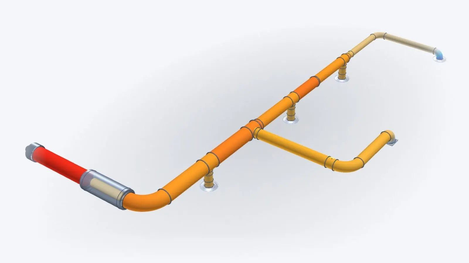
The fan supplies 6,000 m³/h through a Ø500 galvanised sheet steel main duct that runs across the floor. Four circular ceiling diffusers hang from tee spigots and a branch takes air to a meeting room with a grille.
| Terminal | Target airflow | Spigot |
|---|---|---|
| Diffuser 1 | 1,000 m³/h | Tee to Ø250 |
| Room grille | 1,500 m³/h | Ø315 branch with damper |
| Diffuser 2 | 1,000 m³/h | Tee to Ø250 |
| Diffuser 3 | 1,000 m³/h | Tee to Ø250 |
| Diffuser 4 | 1,500 m³/h | End of the duct, Ø400 |
Air at 20 °C and sea level, airtightness class B, non-residential use (offices). Terminals with 30–40 Pa pressure drop at their nominal airflow, from the catalogue.
2. First calculation: the air does not go where it should
| Terminal | Target | Calculated | Deviation |
|---|---|---|---|
| Diffuser 1 | 1,000 m³/h | 824 m³/h | -17.6 % |
| Room grille | 1,500 m³/h | 1,098 m³/h | -26.8 % |
| Diffuser 2 | 1,000 m³/h | 1,069 m³/h | +6.9 % |
| Diffuser 3 | 1,000 m³/h | 910 m³/h | -9.0 % |
| Diffuser 4 | 1,500 m³/h | 2,099 m³/h | +39.9 % |
Diffuser 4, at the end of a straight Ø400 run, takes 40 % too much; the meeting room gets 27 % too little. The app also warns of 8.5 m/s in the main duct, above the 8 m/s recommended for offices because of noise. The fan needs 92 Pa.
3. Sizing by airflow
“Size the network” by maximum velocity: 7 m/s in the main and 4 m/s in the branches, the defaults for non-residential use. The app shows the changes before applying them:
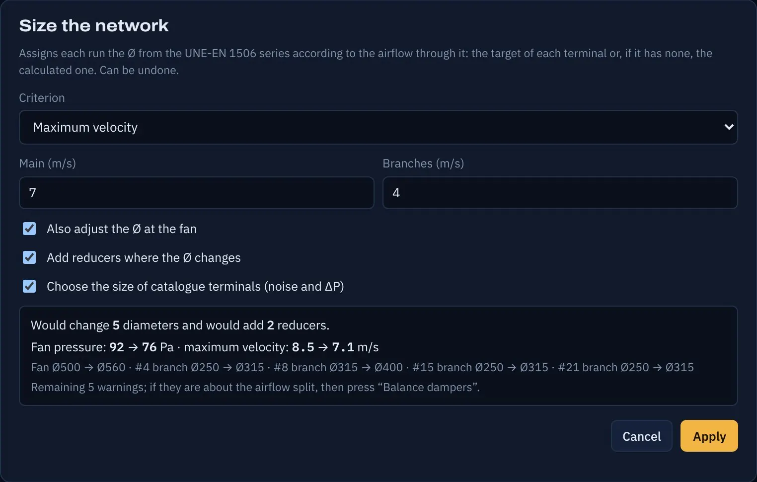
- Fan outlet from Ø500 to Ø560.
- Diffuser spigots from Ø250 to Ø315 and the room branch from Ø315 to Ø400.
- Two new reducers on the main: to Ø450 after the room and to Ø280 before Diffuser 4.
Result: maximum velocity of 7.1 m/s, the fan goes from 92 to 76 Pa (−17 %) and the airflow split ends up between −7 % and +5 %. Better, but the room is still short.
4. Balancing the dampers
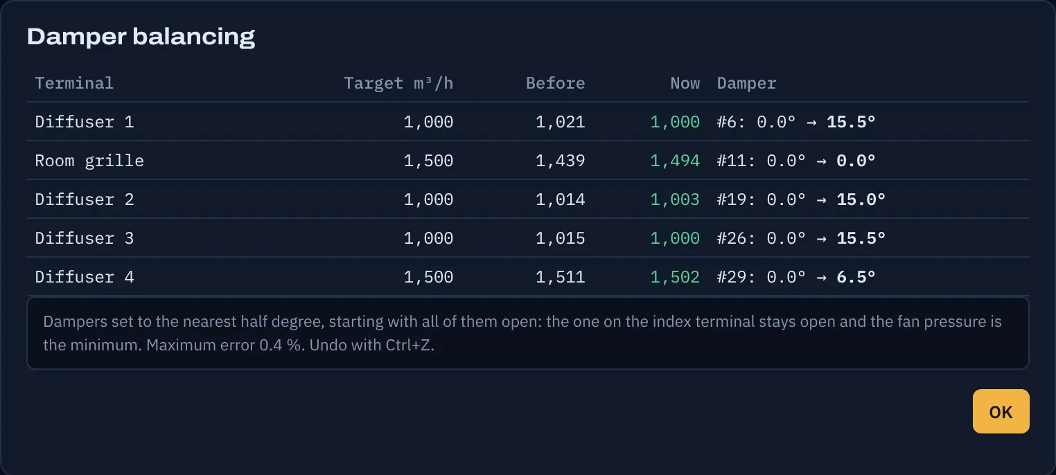
To fine-tune you need something to adjust: a butterfly damper on each diffuser spigot and another on the final run. “Balance dampers” closes them just enough:
| Terminal | Target | Balanced | Deviation | Damper |
|---|---|---|---|---|
| Diffuser 1 | 1,000 m³/h | 1,000 m³/h | 0.0 % | 15.5° |
| Room grille | 1,500 m³/h | 1,494 m³/h | -0.4 % | 0° (open) |
| Diffuser 2 | 1,000 m³/h | 1,003 m³/h | +0.3 % | 15° |
| Diffuser 3 | 1,000 m³/h | 1,000 m³/h | 0.0 % | 15.5° |
| Diffuser 4 | 1,500 m³/h | 1,502 m³/h | +0.1 % | 6.5° |
The room damper stays open: it is the index branch and the one that sets the pressure. The maximum error is 0.4 %. The price of balancing: the fan goes from 76 to 81 Pa.
5. Noise: what the hydraulic calculation does not see
| Room | Limit | Calculated | NR | Excess |
|---|---|---|---|---|
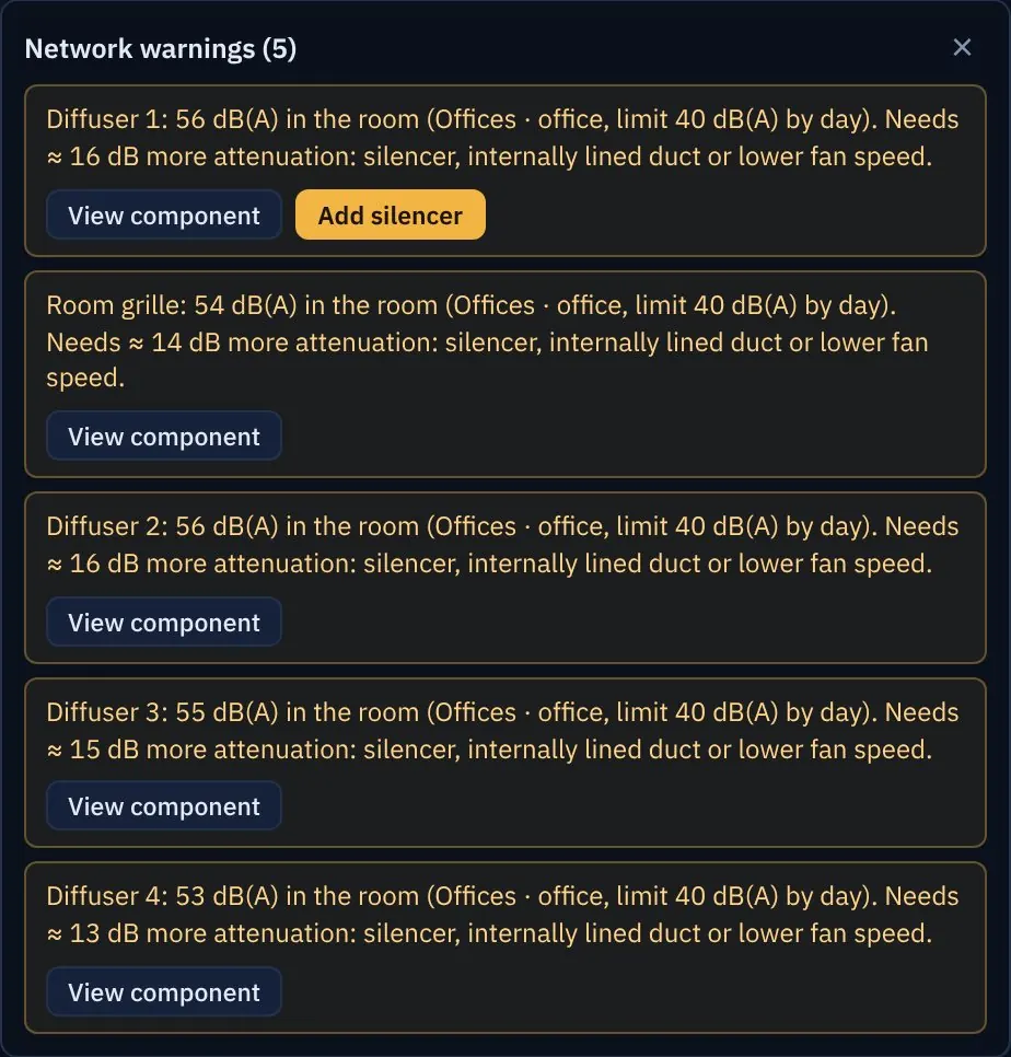
| Diffuser 1 | 40 dB(A) | 56 dB(A) | 60 | 16 dB |
| Room grille | 40 dB(A) | 54 dB(A) | 56 | 14 dB |
| Diffuser 2 | 40 dB(A) | 56 dB(A) | 59 | 16 dB |
| Diffuser 3 | 40 dB(A) | 55 dB(A) | 58 | 15 dB |
| Diffuser 4 | 40 dB(A) | 53 dB(A) | 55 | 13 dB |
Without catalogue data, the app estimates the fan sound power from its airflow and pressure. With that estimate, the noise reaching the rooms through the ducts exceeds the 40 dB(A) limit of the Spanish noise regulation (RD 1367/2007) for offices by 13–16 dB. In an office network without a silencer this is normal, which is why it is worth seeing before installation.
Every noise warning comes with its fix. With “Add silencer”, the app tries generic silencers from 0.6 to 2 m, with and without a pod, and keeps the one that brings every room within its limit with the lowest pressure drop:
- Circular silencer with a central pod (bullet), 2.0 m long, 50 mm absorbent, Ø750 mm casing, just after the first straight run.
- Attenuation: 14 dB at 250 Hz, 25 at 500 Hz, 26 at 1,000 and 2,000 Hz and 24 at 4,000 Hz.
- Pressure drop: 25 Pa at 6.8 m/s.
| Room | Limit | With silencer | NR |
|---|---|---|---|
| Diffuser 1 | 40 dB(A) | 38 dB(A) | 44 |
| Room grille | 40 dB(A) | 38 dB(A) | 41 |
| Diffuser 2 | 40 dB(A) | 38 dB(A) | 43 |
| Diffuser 3 | 40 dB(A) | 37 dB(A) | 43 |
| Diffuser 4 | 40 dB(A) | 37 dB(A) | 40 |
These are generic values (Sabine’s formula for lined ducts) for selection and space planning. The model installed must provide at least that attenuation by octave band: if you have its catalogue, switch the component to “Manufacturer’s data” and the app uses its ΔP and attenuation.
6. The fan and its duty point
With the curve of a Ø560 axial fan (a generic example curve, not a commercial model), the app crosses the fan curve with the system curve, recalculated at several airflows with the dampers in position and the silencer:
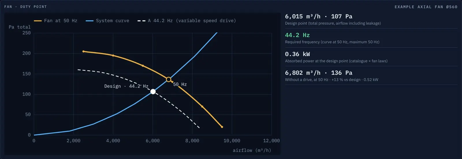
- Design point: 6,015 m³/h (6,000 plus 15 of leakage) at 107 Pa total pressure.
- Without a drive, at 50 Hz: 6,802 m³/h, 13 % too much, at 136 Pa and 0.52 kW.
- With a drive at 44.2 Hz: the design airflow with 0.36 kW, 31 % less power.
- Specific fan power: 193 W/(m³/s), category SFP 0 (EN 16798-3).
7. The report
The PDF report contains design data, terminals, duty point, checks, pressure profile, noise, component details, materials (silencer included) and regulations. Verdict: it meets the calculation criteria, 8 of 8 checks passed.
Summary
| Step | Fan pressure | Maximum velocity | Maximum airflow deviation | Maximum noise |
|---|---|---|---|---|
| First calculation | 92 Pa | 8.5 m/s | 40 % | — |
| Sizing | 76 Pa | 7.1 m/s | 7.4 % | — |
| Balancing | 81 Pa | 6.8 m/s | 0.4 % | 56 dB(A) |
| Silencer | 107 Pa | 6.8 m/s | 0.4 % | 38 dB(A) |
Download the example report11-page PDF with the “EXAMPLE” watermark